How to create a custom Arduino Uno Shield
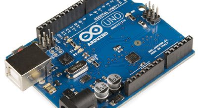
An Arduino shield is a printed circuit board that can be plugged on top of an Arduino development board to extend its capabilities. It is a pre-fabricated module designed to perform a specific function, such as displaying text on an LCD screen, connecting to a wireless network, or controlling a motor.

Shields are a popular way to add functionality to an Arduino because they are easy to use and require minimal wiring. They are also inexpensive and widely available, with many different types of shields available to suit a variety of applications.
There are two main types of Arduino shields: official shields, which are developed and sold by Arduino, and third-party shields, which are developed by other companies or individuals. Official shields are often of higher quality and have more features than third-party shields, but they may also be more expensive.
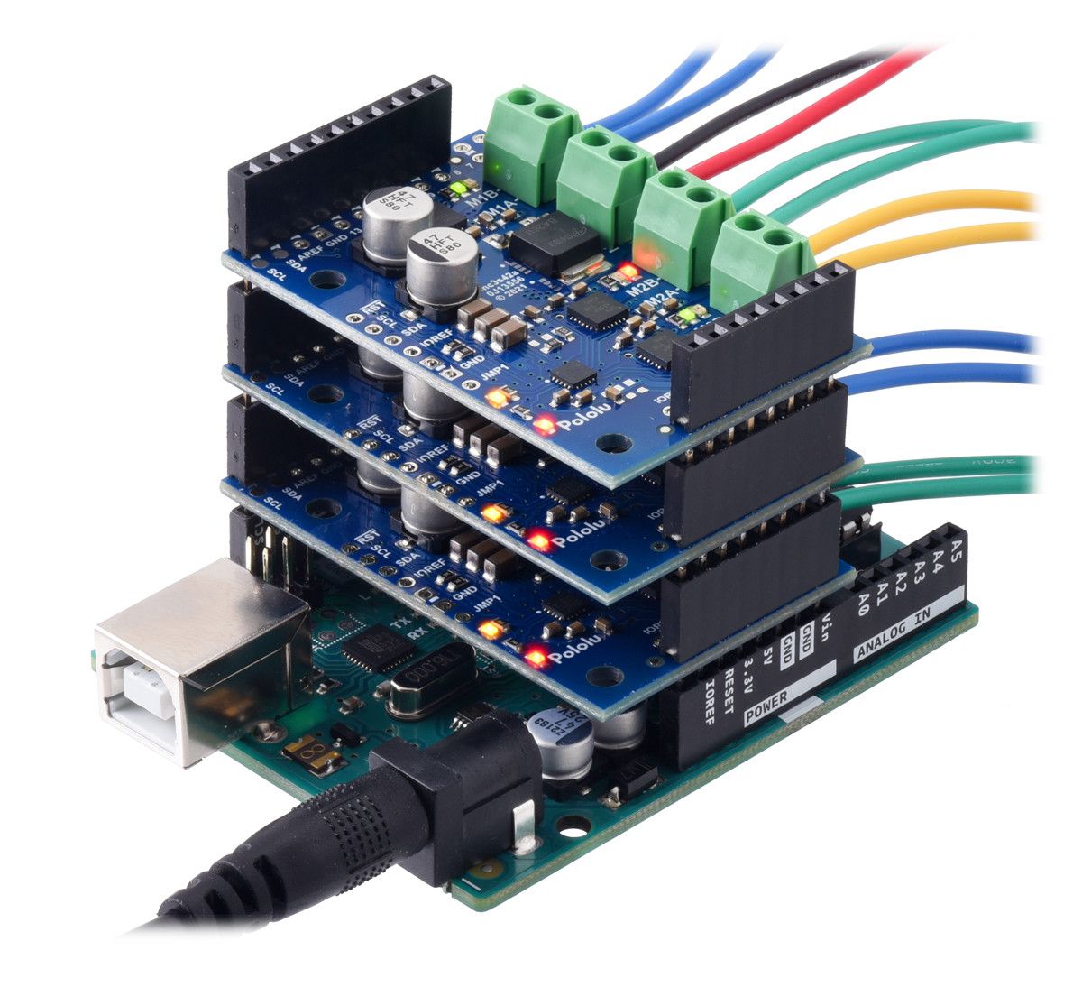
To use a shield with an Arduino, you simply stack the shield on top of the Arduino development board and connect them using the pins on the Arduino board. The pins on the Arduino board and the shield are designed to be compatible with each other, so no special wiring is required. Once the shield is connected, you can use the Arduino programming language and development environment to write code that interacts with the shield and performs the desired function.

There are many different types of Arduino shields available, each with its own unique features and capabilities. Some common types of shields include:
- LCD shields: These shields allow you to connect a character or graphical LCD screen to your Arduino. You can use them to display text, numbers, or even simple graphics.
- Motor shields: These shields allow you to control motors, such as DC motors or stepper motors, using your Arduino. They typically have connectors for multiple motors, as well as built-in H-bridge circuits for driving the motors.
- WiFi shields: These shields allow you to connect your Arduino to a wireless network, enabling you to send and receive data over the internet.
- Ethernet shields: These shields allow you to connect your Arduino to a wired Ethernet network, enabling you to send and receive data over the internet.
- GPS shields: These shields allow you to connect a GPS receiver to your Arduino, enabling you to determine your location and track your movements.
- Audio shields: These shields allow you to connect speakers or headphones to your Arduino, enabling you to play audio files or generate sound using code.
- Sensors shields: These shields allow you to connect various types of sensors to your Arduino, such as temperature sensors, humidity sensors, or pressure sensors.
In addition to these specific types of shields, there are also many general-purpose shields available that provide a variety of additional features, such as additional memory, additional input/output pins, or a prototyping area for building custom circuits.
Overall, Arduino shields are a useful and convenient way to add functionality to an Arduino development board. They are easy to use, widely available, and offer a range of capabilities that can be used in a variety of projects.
What are steps to design and layout a custom Arduino shield?
Designing and laying out a custom Arduino shield can be a challenging but rewarding process. It requires a good understanding of the Arduino platform, as well as some knowledge of printed circuit board (PCB) design and manufacturing. Here are some general steps you can follow to design and layout a custom Arduino shield:
- Determine the function of the shield: The first step in designing an Arduino shield is to determine what function you want it to perform. This will help you decide what components to include on the shield, as well as how to arrange them.
- Choose the components: Once you have a clear idea of the function of the shield, you can start choosing the components that will be used to implement it. Be sure to select components that are compatible with the Arduino platform and that have the necessary features and specifications for your application.
- Create a schematic: A schematic is a diagram that shows the connections between the components on your shield. It is a useful tool for planning out the layout of the PCB and ensuring that all the necessary connections are made.
- Design the PCB layout: With the schematic complete, you can start designing the layout of the PCB. This involves arranging the components on the PCB, routing the connections between them, and ensuring that the layout meets the necessary electrical and mechanical requirements.
- Check the design: Before you finalize the design, it is important to check for any errors or issues that could affect the performance of the shield. This can be done using PCB design software, which can check for things like short circuits, unrouted connections, and clearance violations.
- Fabricate the PCB: Once the design is complete and checked, you can have the PCB fabricated by a manufacturer. This typically involves creating a set of fabrication files, which include the PCB layout and any necessary documentation, and submitting them to the manufacturer.
- Assemble the shield: With the PCB fabricated, you can then assemble the shield by soldering the components onto the PCB. Be sure to follow proper soldering techniques to ensure a reliable connection.
- Test the shield: Once the shield is assembled, it is important to test it to ensure that it is functioning properly. This can be done using the Arduino development environment and some test code to exercise the various features of the shield.
Designing and laying out a custom Arduino shield can be a complex process, but it can also be a rewarding way to learn about electronics and the Arduino platform. By following these steps and using the appropriate tools and resources, you can create a shield that meets your specific needs and requirements.
How would I create a LoRaWAN Arduino shield?

To create a LoRaWAN Arduino shield, you will need to follow a similar process to designing and laying out a custom Arduino shield. Here are some specific steps you can follow to create a LoRaWAN Arduino shield:
- Determine the function of the shield: The first step in designing a LoRaWAN Arduino shield is to determine what function you want it to perform. Do you want it to be able to send and receive data over a LoRaWAN network? Do you want it to be able to connect to sensors or other devices?
- Choose the components: Once you have a clear idea of the function of the shield, you can start choosing the components that will be used to implement it. For a LoRaWAN Arduino shield, you will need to include a LoRaWAN transceiver module, as well as any other components that are necessary for your specific application.
- Create a schematic: A schematic is a diagram that shows the connections between the components on your shield. It is a useful tool for planning out the layout of the PCB and ensuring that all the necessary connections are made.
- Design the PCB layout: With the schematic complete, you can start designing the layout of the PCB. This involves arranging the components on the PCB, routing the connections between them, and ensuring that the layout meets the necessary electrical and mechanical requirements.
- Check the design: Before you finalize the design, it is important to check for any errors or issues that could affect the performance of the shield. This can be done using PCB design software, which can check for things like short circuits, unrouted connections, and clearance violations.
- Fabricate the PCB: Once the design is complete and checked, you can have the PCB fabricated by a manufacturer. This typically involves creating a set of fabrication files, which include the PCB layout and any necessary documentation, and submitting them to the manufacturer.
- Assemble the shield: With the PCB fabricated, you can then assemble the shield by soldering the components onto the PCB. Be sure to follow proper soldering techniques to ensure a reliable connection.
- Test the shield: Once the shield is assembled, it is important to test it to ensure that it is functioning properly. This can be done using the Arduino development environment and some test code to exercise the various features of the shield.
Creating a LoRaWAN Arduino shield can be a complex process, but it can also be a rewarding way to learn about electronics and the Arduino platform. By following these steps and using the appropriate tools and resources, you can create a shield that meets your specific needs and requirements.


